Top
Information to Know Before Starting
Before starting to use these configuration notes, complete the following table to make sure you have the required information to complete the different steps.
| Information | Value | Used in Step |
|---|---|---|
| Temporary IP address used by your Mediatrix unit to communicate with the Management Interface. | DHCP server- provided IP address | Logging on to the Mediatrix Unit Web Interface |
| Final Static LAN IP address as defined in your network address range. | Configuring the Uplink Network Interface | |
| Static Default Router IP address of the Uplink Network Interface | Configuring the Default Network Gateway to a Static IP Address | |
| IP address of each DNS server | Configuring the Domain Name Server (DNS) | |
| IP address of each SNTP server | Configuring the SNTP Server to a Static IP Address | |
| Public IP address of router/firewall | Configuring the uplink_s Signaling Interface | |
| IP address of the IP PBX | Configuring the lan_ip_pbx_ca Call Agent | |
| Make sure you have the latest rulesets from the Media5 Support Portal |
|
Importing Rulesets |
Top
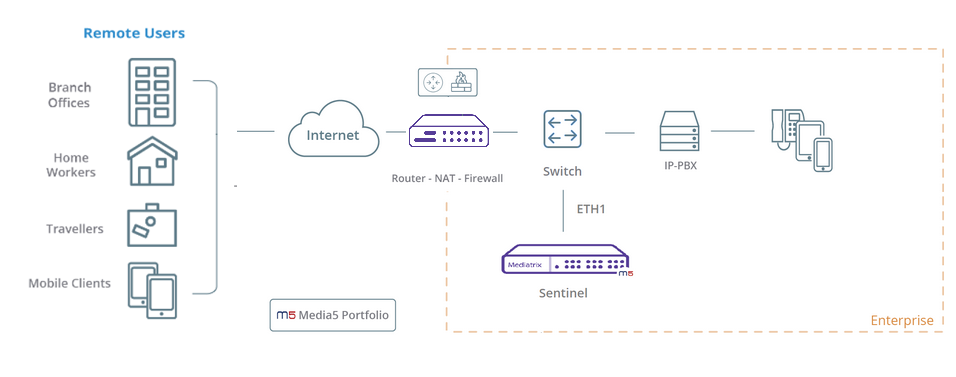
Remote Users - Sentinel in the LAN
- The remote users are using SIP endpoints on the public Internet or behind a NAT on the public Internet.
- The SIP endpoints register on a PBX located in the LAN of the office, using the Sentinel as an outbound proxy.
- The Sentinel consults the SIP endpoints to generate enough traffic and maintain the firewall open.
- The Sentinel protects the local PBX from Internet threats.
- The Sentinel is in the LAN, behind the enterprise NAT
Top
Important Information on NAT, Interfaces, and Ports
Since this scenario uses only one physical network interface (ETH1) for communicating both with the ITSP/Public Internet and the IP-PBX, different ports will need to be assigned to the signaling and media interfaces for the Sentinel to differentiate the traffic.
- On the ITSP/Public Internet side, port 5060 is used for signaling with the 20000-20999 range for media. The router/firewall will need to be set up to allow connections from the ITSP/Public Internet on these ports, and set up port forwarding to the Sentinel internal IP address.
- On the IP PBX side, port 5064 is used for signaling with the 21000-21999 range for media. Depending on the PBX, this can be accomplished by either creating a SIP trunk on an alternate port, or in the Outbound Proxy configuration.
Top
Logging on to the Mediatrix Unit Web Interface
Top
Configuring the Uplink Network Interface

Top
Configuring the Default Network Gateway to a Static IP Address

Top
Configuring the Domain Name Server (DNS)
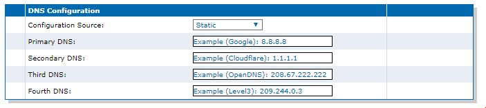
- Go to Network/Host.
- In the DNS Configuration table, form the Configuration Source selection list, select Static.
- For each DNS used, enter the IP address of the DNS.
- Click Apply.
Top
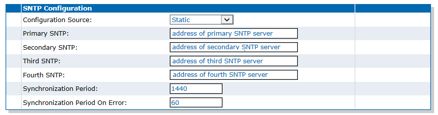
Configuring the SNTP Server to a Static IP Address
Top
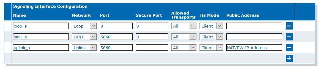
Configuring the uplink_s Signaling Interface
Top
Configuring the uplink_m Media Interface

Top
Configuring the pbx_s Signaling Interface
-
In the Signaling Interface Configuration table, click
 to create a new interface.

Top
Configuring the pbx_m Media Interface
-
In the Media Interface Configuration
table, click to create a new interface.

Top
Importing Rulesets

Top
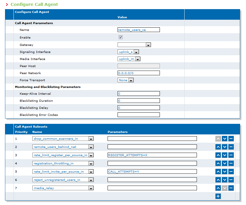
Configuring the remote_users_ca Call Agent
-
In the Call Agent Configuration
table, click
 located on the same row as remote_users_ca.
-
In the Call Agent Rulesets table,
click .
Note:You can ignore the "Invalid configuration" and "Unknown ruleset" warnings. They will disappear when the configuration is saved.
-
Click
-
Click
-
Click
-
Click
-
Click
-
Click
Top
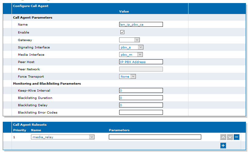
Configuring the lan_ip_pbx_ca Call Agent
-
In the Call Agent Configuration
table, click next to lan_ip_pbx_ca.
-
In the Call Agent Rulesets table,
click .
Note:You can ignore the "Invalid configuration" and "Unknown ruleset" warnings. They will disappear when the configuration is saved.
Top
Associating Routing Rulesets to Your Configuration
-
Click .
Note:You can ignore the "Invalid configuration" and "Unknown ruleset" warnings. They will disappear when the configuration is saved
-
Click .
Note:You can ignore the "Invalid configuration" and "Unknown ruleset" warnings. They will disappear when the configuration is saved

Top
Configuring Your Mobile/Remote Phones
- Set the SIP server to the (private) IP address or FQDN of the IP PBX in the main office.
- Set the outbound proxy to the public IP address or FQDN of the main office Router/Firewall.
- Set the username and password according to the IP PBX configuration.
- Test inbound/outbound calls between remote extensions.
- Test inbound/outbound calls between remote and internal extensions.
- Test inbound/outbound calls between remote extensions and the PSTN.
- Test all the IP-PBX telephony services on the remote extensions.
Top
Adding Local Firewall Rules - Optional
-
In the Local Firewall Rules table,
click .
-
Click .
-
Click .
-
Click .
-
Click .
-
Click .
-
Click .
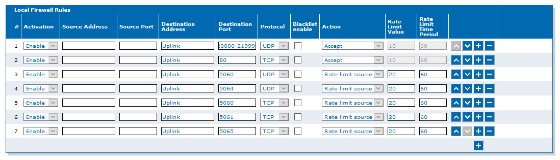
Calls will only reach the Mediatrix unit if they are using SIP protocol (ports 5060,5061 for remote users and 5064,5065 for IP PBX) or RTP protocol (ports 20000-21999). The Local Firewall rules will open the ports intended for:
- RTP on the Remote Users side (20000-20999) and on IP PBX side (21000-21999) (Step 3)
- Web access (Step 5)
- UDP for SIP signaling on the Remote Users side (Step 7)
- UDP for SIP signaling on the IP PBX side (Step 9)
- TCP for SIP signaling on the Remote Users side (Step 11)
- TCP for secure SIP signaling on the Remote Users side (Step 13)
- TCP for secure SIP signaling on the IP PBX side (Step 15)
Top
Available Documentation
Top
Copyright Notice
Copyright © 2026 Media5 Corporation.
This document contains information that is proprietary to Media5 Corporation.
Media5 Corporation reserves all rights to this document as well as to the Intellectual Property of the document and the technology and know-how that it includes and represents.
This publication cannot be reproduced, neither in whole nor in part, in any form whatsoever, without written prior approval by Media5 Corporation.
Media5 Corporation reserves the right to revise this publication and make changes at any time and without the obligation to notify any person and/or entity of such revisions and/or changes.